|
Beams-doc-2618 |
|---|
|
Beams-doc-2618 |
|---|
On January 11, 2007 a study was done to examine the effect of the MI8 Collimator system on Main Injector operation. New collimator scans were used to establish the location where 1% of the Booster beam was scraped using only one collimator edge. Then the position was set to scrape with two edges (one horizontal and one vertical) on each of the four MI8 Collimators where the position was chosen at the point where 1/2% loss was observed when only one edge was used. The combination scraped about 3.5% of the beam. A vertical aperture scan at VP301 before, with collimators in place, and after their removal documented the improved vertical size of the beam. Measurements of the losses around the Main Injector using the Loss Monitor Program demonstrated reduced losses as well. Based on these new collimator scans, a proposal for initial operation will be formulated.
Information on the MI8 Collimation system is available in:
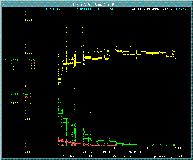
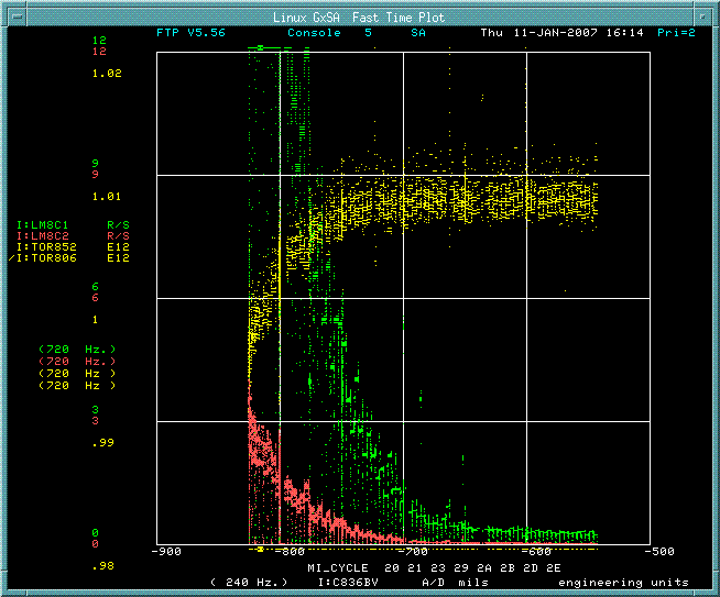
Operation for NuMI and PBar production were running at 31E12 protons in 7 batches (12 turns on $14 and $19) for typical operation on January 11. Under these conditions we find that the transmission down the MI8 line can be measured well using I:TOR852/I:TOR806 which which has a range of 0.3% variability and averages about 1.008. Scans of the losses on I:LM8C1 (for 836) vs. collimator position were done on Dec 12. Similar scans of the losses on LM8C3 (for 838) were done on Dec 19. Scans were repeated on January 3 with an extended range of losses and with the transmission recorded on the same graph. Using this information we chose which side of each collimator axis to use for this collimation study. We repeated the transmission and loss monitor study to establish more closely the collimator location which scraped 1% of the beam, documented the loss monitor reading for that location and determined the collimator position for which the Loss Monitor read one half of that loss to provide a 1/2% scraping location.
| Image | Description |
|---|---|

|
Scan of transmission and loss vs. horizontal position of Collimator A (836 upstream). Transmission is ratio of I:TOR806/I:TOR852. Loss readings are from LM8C1 (836 marble mask) and LM8C2 (836 tunnel wall). One identifies the collimator position for 1% loss and notes the loss monitor reading using the more sensitive loss monitor. The positions for 1/2%, 1/4%, and 1/8% loss are identified assuming that the loss monitor reading is linear. Results are in tables below. |

|
Scan of transmission and loss vs. vertical position of Collimator D (838 downstream). Transmission is ratio of I:TOR806/I:TOR852. Loss readings are from LM8C3 (838 marble mask) and LM8C4 (838 tunnel wall). |
Measurements of the loss edges shown in the next table were used as an initial calibration of the Loss Monitors. These and other images were (re-)examined to set the scales for the next measurement of loss edges. The first five columns provide primary data. The TOR806 reading is a nominal one which is then used to convert the loss fraction to protons lost which are then used in the sensitivity calculations. the same proceedure is used in the table for the January 11 scans. One finds that the sensitivities in that table are more uniform which should be taken as a reflection of the more appropriate graph scales used for that measurement.
| Motor Drive | Date | Position | LM8C1 | Loss Tran | I:TOR806 | Loss | Sensitivity | ||
| mils | Rad/sec | p / 10 R/s | R/s / E11 | ||||||
| I:C836AH | 29-Dec-06 | -950 | 10 | 0.04 | 4.80E+12 | 1.92E+11 | 1.92E+11 | 5.21 | |
| I:C836AH | 29-Dec-06 | 650 | 10 | 0.03 | 4.80E+12 | 1.44E+11 | 1.44E+11 | 6.94 | |
| I:C836BH | 29-Dec-06 | -900 | 10 | 0.01 | 4.80E+12 | 4.80E+10 | 4.80E+10 | 20.83 | |
| I:C836BH | 29-Dec-06 | 600 | 10 | 0.01 | 4.80E+12 | 4.80E+10 | 4.80E+10 | 20.83 | |
| I:C836AV | 3-Jan-07 | -670 | 10 | 0.025 | 4.80E+12 | 1.20E+11 | 1.20E+11 | 8.33 | |
| I:C836AV | 3-Jan-07 | 950 | 10 | 0.02 | 4.80E+12 | 9.60E+10 | 9.60E+10 | 10.42 | |
| I:C836BV | 3-Jan-07 | -800 | 20 | 0.02 | 4.80E+12 | 9.60E+10 | 4.80E+10 | 20.83 | |
| I:C836BV | 3-Jan-07 | 750 | 20 | 0.025 | 4.80E+12 | 1.20E+11 | 6.00E+10 | 16.67 | |
| LM8C3 | |||||||||
| Rad/sec | |||||||||
| I:C838AH | 3-Jan-07 | -825 | 10 | 0.07 | 4.80E+12 | 3.36E+11 | 3.36E+11 | 2.98 | |
| I:C838AH | 3-Jan-07 | 700 | 10 | 0.04 | 4.80E+12 | 1.92E+11 | 1.92E+11 | 5.21 | |
| I:C838BH | 3-Jan-07 | -800 | 20 | 0.005 | 4.80E+12 | 2.40E+10 | 1.20E+10 | 83.33 | |
| I:C838BH | 3-Jan-07 | 600 | 20 | 0.005 | 4.80E+12 | 2.40E+10 | 1.20E+10 | 83.33 | |
| I:C838AV | 3-Jan-07 | -850 | 10 | 0.04 | 4.80E+12 | 1.92E+11 | 9.60E+10 | 5.21 | |
| I:C838AV | 3-Jan-07 | 750 | 10 | 0.035 | 4.80E+12 | 1.68E+11 | 8.40E+10 | 5.95 | |
| I:C838BV | 3-Jan-07 | -850 | 20 | 0.015 | 4.80E+12 | 7.20E+10 | 3.60E+10 | 27.78 | |
| I:C838BV | 3-Jan-07 | 650 | 20 | 0.01 | 4.80E+12 | 4.80E+10 | 2.40E+10 | 41.67 |
Based on the Scans on January 11, we identify the following edges for 1% and 1/2% loss. These 1/2% loss edges are used in subsequent studies.
| Motor Drive | Date | Position | LM8C1 | Loss Tran | I:TOR806 | Loss | Sensitivity | |||
| mils | Rad/sec | p / 10 R/s | R/s / E11 | |||||||
| I:C836AH | 11-Jan-07 | -877 | 4 | 0.01 | 4.80E+12 | 4.80E+10 | 4.80E+10 | 8.33 | ||
| I:C836AH | 11-Jan-07 | -830 | 2 | 0.005 | 4.80E+12 | 2.40E+10 | 2.40E+10 | 8.33 | ||
| I:C836BH | 11-Jan-07 | 622 | 6 | 0.01 | 4.80E+12 | 4.80E+10 | 4.80E+10 | 12.50 | ||
| I:C836BH | 11-Jan-07 | 550 | 3 | 0.005 | 4.80E+12 | 2.40E+10 | 2.40E+10 | 12.50 | ||
| I:C836AV | 11-Jan-07 | 861 | 4 | 0.01 | 4.80E+12 | 4.80E+10 | 4.80E+10 | 8.33 | ||
| I:C836AV | 11-Jan-07 | 839 | 2 | 0.005 | 4.80E+12 | 2.40E+10 | 2.40E+10 | 8.33 | ||
| I:C836BV | 11-Jan-07 | -820 | 3 | 0.01 | 4.80E+12 | 4.80E+10 | 4.80E+10 | 6.25 | ||
| I:C836BV | 11-Jan-07 | -800 | 1.5 | 0.005 | 4.80E+12 | 2.40E+10 | 2.40E+10 | 6.25 | ||
| LM8C3 | ||||||||||
| Rad/sec | ||||||||||
| I:C838AH | 11-Jan-07 | 638 | 4 | 0.01 | 4.80E+12 | 4.80E+10 | 4.80E+10 | 8.33 | ||
| I:C838AH | 11-Jan-07 | 600 | 2 | 0.005 | 4.80E+12 | 2.40E+10 | 2.40E+10 | 8.33 | ||
| I:C838BH | 11-Jan-07 | -811 | 9.16 | 0.01 | 4.80E+12 | 4.80E+10 | 4.80E+10 | 19.08 | ||
| I:C838BH | 11-Jan-07 | -790 | 4.6 | 0.005 | 4.80E+12 | 2.40E+10 | 2.40E+10 | 19.17 | ||
| I:C838AV | 11-Jan-07 | 739 | 3.55 | 0.01 | 4.80E+12 | 4.80E+10 | 4.80E+10 | 7.40 | ||
| I:C838AV | 11-Jan-07 | 700 | 1.78 | 0.005 | 4.80E+12 | 2.40E+10 | 2.40E+10 | 7.42 | ||
| I:C838BV | 11-Jan-07 | -822 | 9 | 0.01 | 4.80E+12 | 4.80E+10 | 4.80E+10 | 18.75 | ||
| I:C838BV | 11-Jan-07 | -780 | 4.55 | 0.005 | 4.80E+12 | 2.40E+10 | 2.40E+10 | 18.96 |
| Image | Description |
|---|---|
| Vertical Scan of aperture at Q301 before collimators in MI8 were positioned to scrape beam halo. Region with no losses is less than 2 mm wide. | |
| Vertical Scan of aperture at Q301 with collimator in MI8 line scraping about 3.5% of Booster Intensity. Operation was at about 4.6E12 for NuMI batches. Region with no losses in now about 6 mm wide. | |
| Scan at Q301 after positioning MI8 collimators to no longer scrape. This was superimposed on above image of aperture with scraping. |
| Main Injector Loss Control With MI8 Collimation |
|---|

|
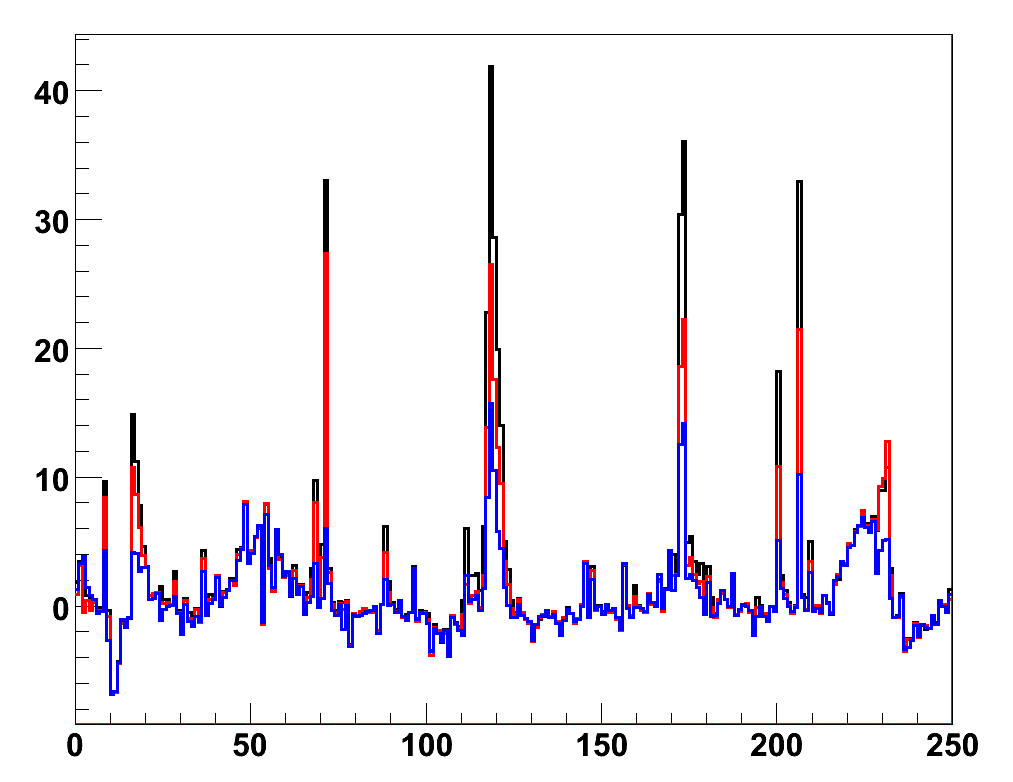
Ring-wide losses at 8 GeV in the MI. The horizontal axis is a loss monitor index around the circumference - the peaks occur at the lambertson locations. The vertical axis is loss in R/s, integrated over a approx. 0.04s timeslice after one of the injections.
The black trace is with all MI-8 collimators in the out position, the red trace has the horizontal collimators in, and the blue trace has both H and V collimators in.
| Motor Drive | Date | Position | LM8C1 | Loss Tran | I:TOR806 | Loss | Sensitivity | |||
| mils | Rad/sec | p / 10 R/s | R/s / E11 | |||||||
| I:C836AH | 11-Jan-07 | -800 | 1 | 0.0025 | 4.80E+12 | 1.20E+10 | 1.20E+10 | 8.33 | ||
| I:C836AH | 11-Jan-07 | -767 | 0.5 | 0.00125 | 4.80E+12 | 6.00E+09 | 6.00E+09 | 8.33 | ||
| I:C836BH | 11-Jan-07 | 493 | 1.5 | 0.0025 | 4.80E+12 | 1.20E+10 | 1.20E+10 | 12.50 | ||
| I:C836BH | 11-Jan-07 | 430 | 0.75 | 0.00125 | 4.80E+12 | 6.00E+09 | 6.00E+09 | 12.50 | ||
| I:C836AV | 11-Jan-07 | 805 | 1 | 0.0025 | 4.80E+12 | 1.20E+10 | 1.20E+10 | 8.33 | ||
| I:C836AV | 11-Jan-07 | 777 | 0.5 | 0.00125 | 4.80E+12 | 6.00E+09 | 6.00E+09 | 8.33 | ||
| I:C836BV | 11-Jan-07 | -684 | 0.75 | 0.0025 | 4.80E+12 | 1.20E+10 | 1.20E+10 | 6.25 | ||
| I:C836BV | 11-Jan-07 | -637 | 0.038 | 0.00125 | 4.80E+12 | 6.00E+09 | 6.00E+09 | 0.63 | ||
| LM8C3 | ||||||||||
| Rad/sec | ||||||||||
| I:C838AH | 11-Jan-07 | 557 | 1 | 0.0025 | 4.80E+12 | 1.20E+10 | 1.20E+10 | 8.33 | ||
| I:C838AH | 11-Jan-07 | 500 | 0.5 | 0.00125 | 4.80E+12 | 6.00E+09 | 6.00E+09 | 8.33 | ||
| I:C838BH | 11-Jan-07 | -733 | 2.3 | 0.0025 | 4.80E+12 | 1.20E+10 | 1.20E+10 | 19.17 | ||
| I:C838BH | 11-Jan-07 | -697 | 1.15 | 0.00125 | 4.80E+12 | 6.00E+09 | 6.00E+09 | 19.17 | ||
| I:C838AV | 11-Jan-07 | 663 | 0.89 | 0.0025 | 4.80E+12 | 1.20E+10 | 1.20E+10 | 7.42 | ||
| I:C838AV | 11-Jan-07 | 630 | 0.45 | 0.00125 | 4.80E+12 | 6.00E+09 | 6.00E+09 | 7.50 | ||
| I:C838BV | 11-Jan-07 | -736 | 2.28 | 0.0025 | 4.80E+12 | 1.20E+10 | 1.20E+10 | 19.00 | ||
| I:C838BV | 11-Jan-07 | -677 | 1.14 | 0.00125 | 4.80E+12 | 6.00E+09 | 6.00E+09 | 19.00 |
Using the highlighted values in the above table (1/8% loss) we set
collimators to scrape the beam. Assuming that when scraping the
edges, one can add linearly the horizontal and vertical effects, one
would expect losses of about 2.1 R/s at 836 and 3.25 R/s at 838. We
observed loss monitor readings using LM8C1 of about 1 R/s (836) and
using LM8c3 of about 2 R/s (838) which are about 1/2 of a simple sum.
however we expected a total loss of about 1% (8 x 1/8) but the ratio
I:TOR806/I:TOR852 went from 1.0075 only down to 1.0050
The following time plot shows the loss monitor readings as the collimators
were positioned. Spiked response came from study pulses on a $2B cycle
(which accelerates 7 Booster batches).
We expect that operation with MI8 collimators will substantially reduce integrated losses at selected locations around the Main Injector. It will certainly reduce losses in time intervals just following injection. We will be applying increasing levels of collimation for HEP operation and developing ways to observe the effects on loss monitor readings. We will also monitor changes in residual radiation where we expect to see improved conditions with fewer hot locations.