| Beams-doc-4457 |
|---|
| Beams-doc-4457 |
|---|
The collimation system for the Main Injector which was installed in 2007 (see Beams-doc-2881) employed a primary collimator motion system which was installed in 2006 having been re-purposed at least twice. It was not ever optimal and if it had failed, replacement would have been painful and would have incurred a large radiation dose. A replacement system has been built and installed during the 2012-2013 Fermilab Facility Shutdown. We will provide a description of that system including installation and alignment information and motor control details. Some comments on operational considerations will follow.
The scattering foil is 0.010" thick. The mount provides an open edge which is positioned to approach the radially inside edge of the Main Injector beam. The offset from the beam center to the collimator foil edge is controlled by the position of the primary collimator in combination with a orbit bump (time bump) which sets the position of the beam at MI230. When withdrawn to the out limit, the foil is outside of the beam pipe aperture but if it is sufficiently extended toward the inside, it can be damaged by circulating beam. At its in limit switch, the foil edge it at (approximately) beam line center.
Before providing additional details, let us document the most useful information: where should we place the collimator? The motor control system employs limit switches which have been set so that at the OUT limit, the collimator edge is just outside of the beam pipe on the radial inside (aisle side) and at the collimator IN limit, the edge of the collimator is at about the center of the beam pipe. Nominal position of the beam pipe center is along the centerline of the MI230 quadrupole. Since the beam orbit is distorted for collimation, the beam edge can be moved to the edge of the collimator such that small details of the beam pipe centering are not operationally important. Motor control parameters are
-I:CPH230     MI-30 Q230 Primry Target    <      > -2386   Mils OU.O
-I:CPHPL      CPH230 Positive Limit         0        0     step
-I:CPHNL      CPH230 Negative Limit       -2386    -2386   step
where CPH230 is the motor control device. Values entered between the < > are the requested steps when followed by an s or the desired position (don't use that). Units are mils (0.001"). A left mouse click in the control region at the end of the line will invoke the digital status:
  Digital Status

  Reset
  On
  Off
  Positive
  Negative
When the out limit switch is engaged, the final character of the line
will show O (as shown) and employing the 'Reset' option will load the
position variable with the value: I:CPHNL. When the relation between
the reading (current position based on steps requested) and actual
position is in doubt, move to the out limit and employ this option.
When the in limit switch is engaged (as indicated by I in the
next-to-last column), the similar reset action will load I:CPHPL but
this means that the collimator edge is at the center of the beam pipe.
We should avoid this since the beam is likely to damage the
collimator.
The limit switches were mounted in this configuration in July 2013. The visual scale (see Figure a (C) below) reads ~10 mm at the OUT limit and ~70 mm at the IN limit. The visual readings, the limit switch operation, and the number of steps between limits was confirmed on 17 September 2013.
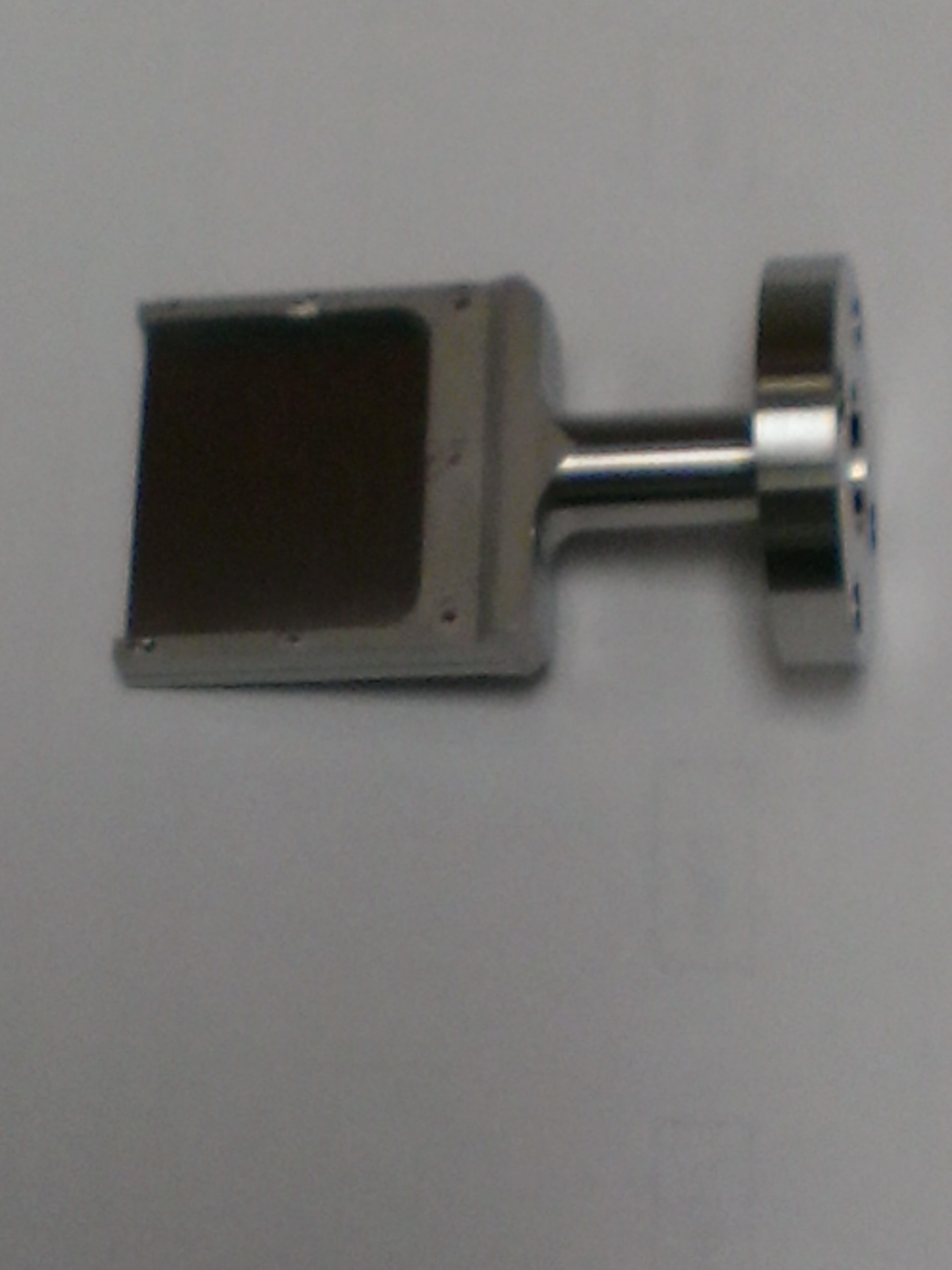
As shown in Fig 1(A), a stainless steel bracket is used to mount the primary collimator tungsten foil. It is mounted on the drive system which provides radial motion along a fixed horizontal axis. The open area of the foil is 1.125" high by 1" deep (28.58 by 25.4 mm). The beam pipe aperture is much larger but the primary collimator is placed near a horizontally focusing quadrupole so the vertical beta function is small and the maximum vertical beam size is smaller than this (See Aperture Requirements section below).
The essential motion system features are established by the elliptical vacuum pipe welded to the pipe which holds the motion system as seen below.
| Picture | Comments |
|---|---|
|
(A) Primary Collimator Foil in Holder. This 10 mil (0.25 mm or 0.010" tungsten (W) foil is pinned to the stainless steel 'C' frame. The open edge is 1.125" (28.575 mm) high. This image is of the spare foil holder. Drawing number 9502.000-MB-463481 describes the foil holder. Drawing number 9502.000-MB-463480 describes the tungsten foil. |
|
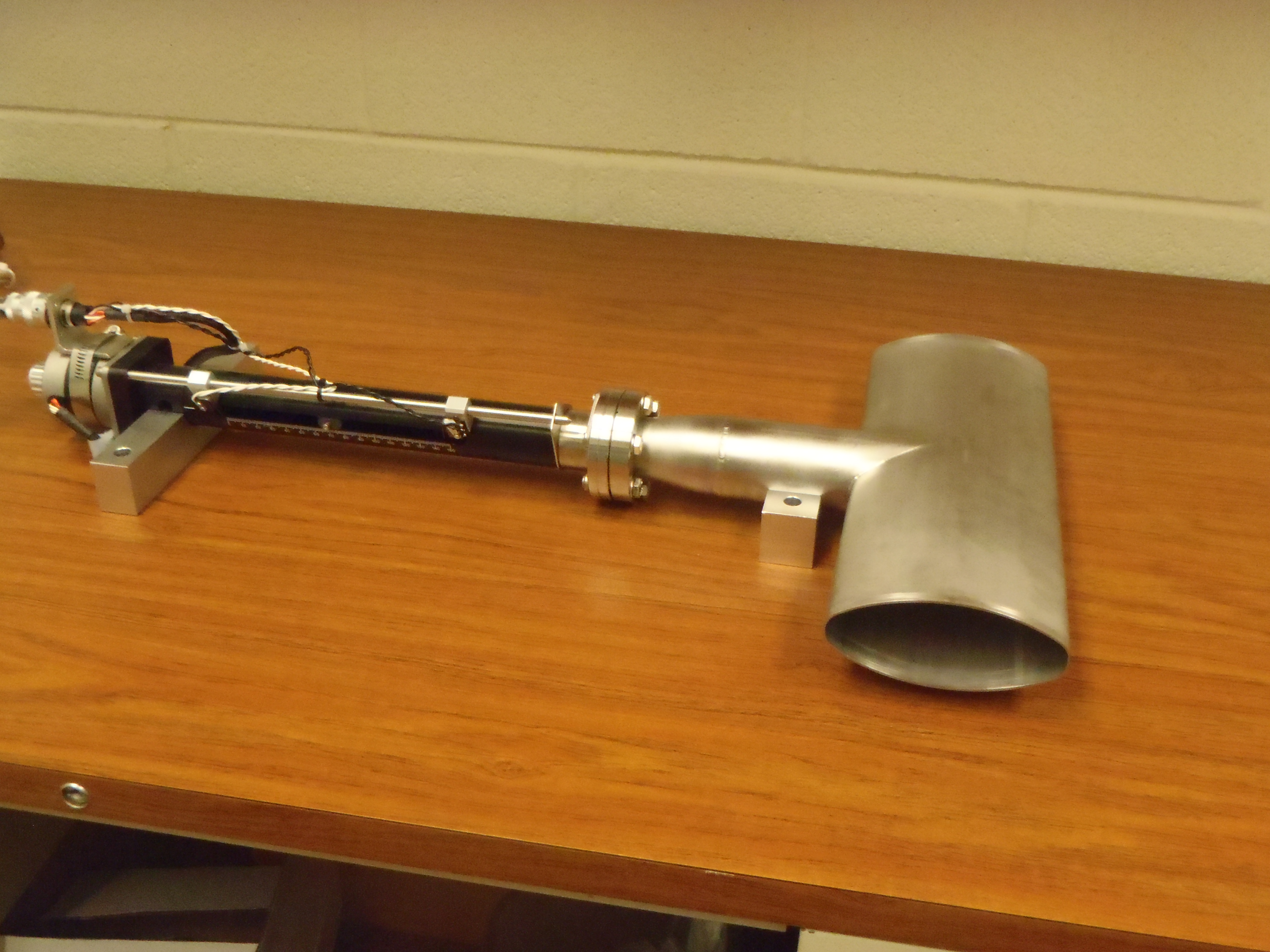
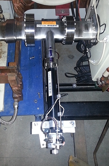
(B) Primary Collimator motion positioning system attached to section of standard Main Injector elliptical beam pipe. Motion is provided by VG SCIENTA model ZLDS215M Linear Translator -- 150 mm stroke. More information may be found at VG SCIENTA Document Number UI32194A As shown below, this pipe is securely but not precisely attached to the vacuum system using flanges and bellows. |
|
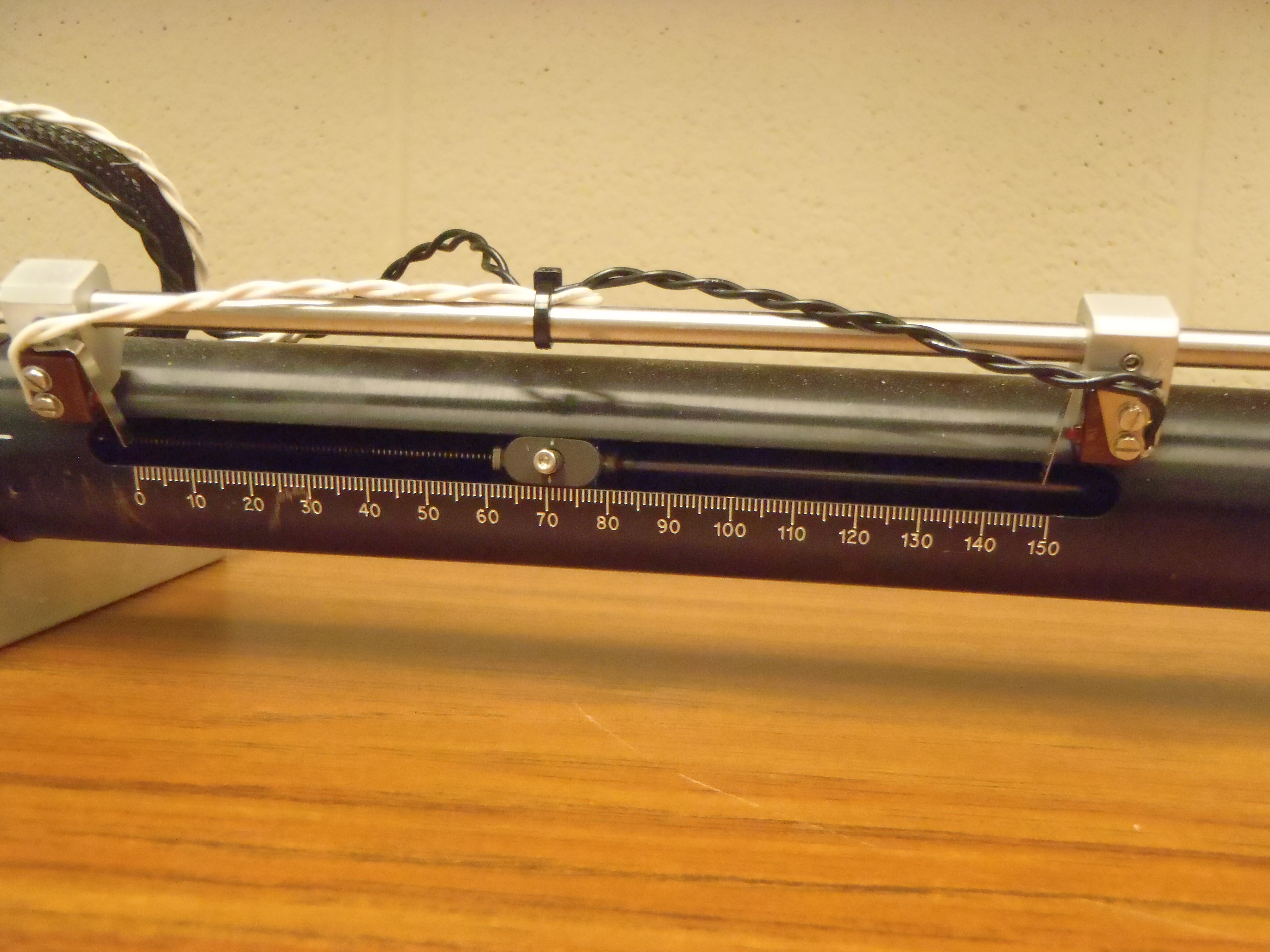
(C) Closer view of new assembly showing visual scale in mm units. Screw-head is indicator for position. Limit switches were re-positioned after this photograph was taken. |
|
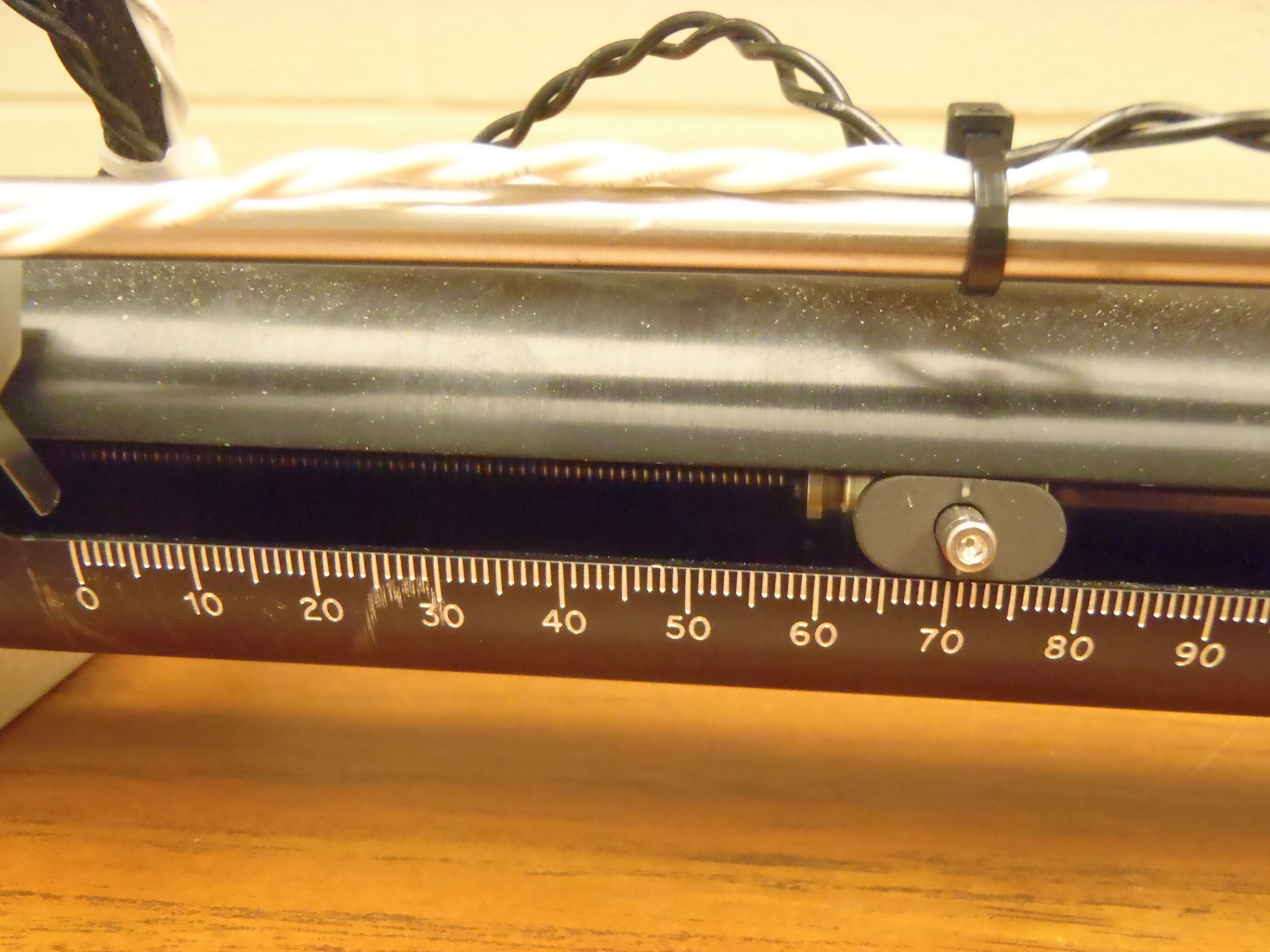
(D) Still closer view of new assembly showing visual scale in mm units. At this position, the blade would extend a bit beyond the beam pipe center so the limit switch has been set to exclude this location. |
| Picture | Comments |
|---|---|

|
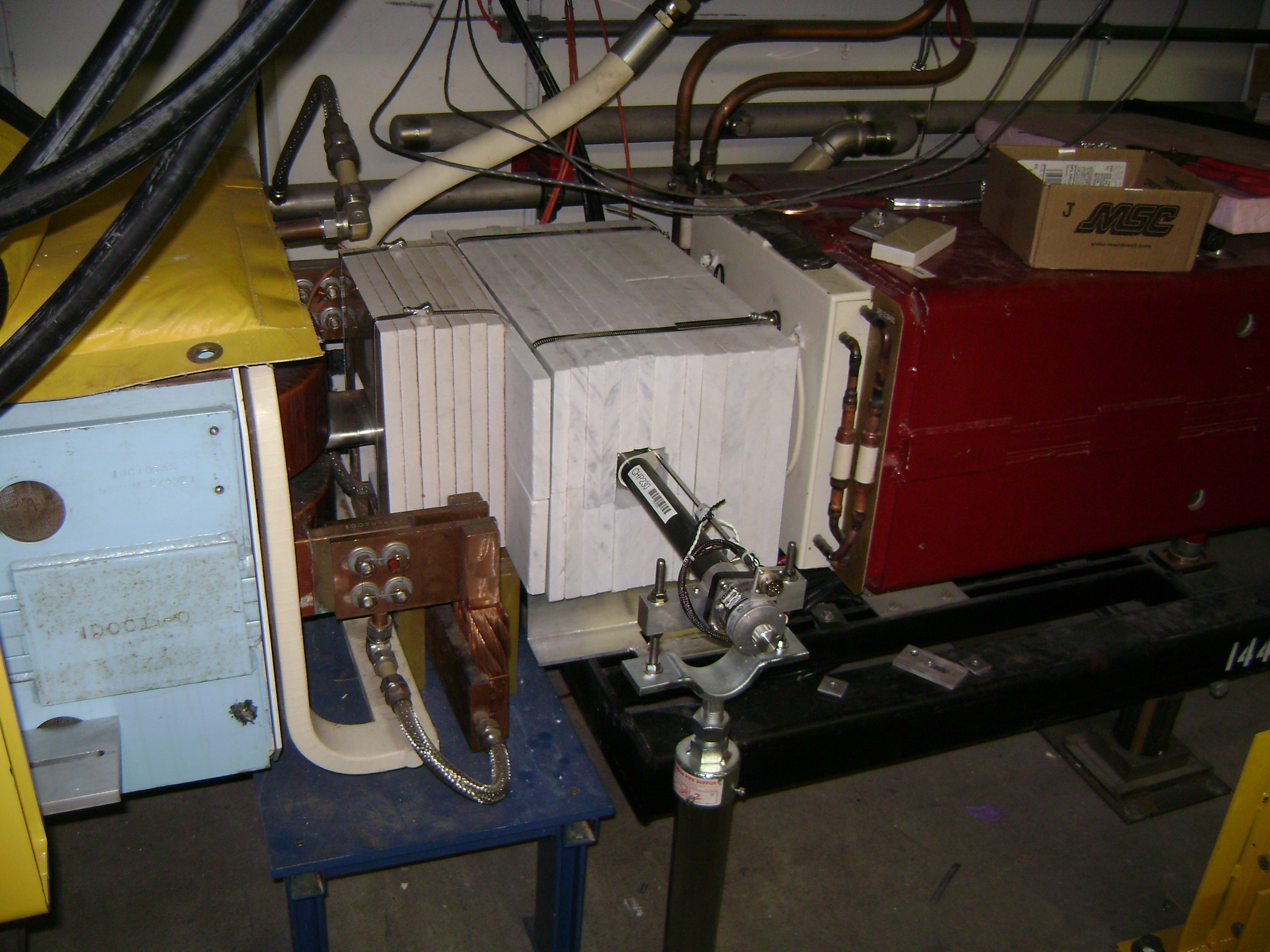
(A) Primary collimator with vacuum assembly and support after installation on 2/27/2013. View is from aisle to show support and adjustments. |
|
(B) Primary collimator vacuum assembly and motion system in view from the top prior to shielding installation (2/27/2013). Drawing 9502-000-ME-463469-B documents the assembly while Drawing 9502-000-MD-463471 describes the vacuum part. |

|
(C) Primary collimator vacuum assembly side view revealing vertical alignment offset. |

|
(D) Primary collimator with shielding as viewed from aisle. |
|
(E) Primary collimator system as viewed from aisle (upstream). Two sections of marble shielding to reduced radiation on magnet coils and motion system motor are held with stainless steel hose clamps. Yellow stand in lower right holds the rails (not installed when photo was taken) which protect the installation from traffic mishaps. |
The design was chosen to allow flexible operation with simple
implementation. The radial motion system could easily allow setting
the foil edge at any radial location from beam pipe center to outside
of the beam pipe aperture (some figures available in attached survey).
The previous primary collimator motion system employed a large box
which is undesirably since beam-induced rf can be stored and induce
undesired effects. We observed that the placement of this collimator
near a horizontally focusing quadrupole implies that the vertical beta
function is only about 10 m. In the MI dipoles, the vertical aperture
is 2" (50.8 mm) high but this must be adequate for vertical beta
function values near the horizontally defocusing quadrupole of greater
than 50 m (53 m - 60 m typical). This implies that the required
vertical extent of the collimator foil need be no larger than 2" x
sqrt (10/50) = 0.8944' (22.72 mm). As shown in Fig. 1(A), the 1.125"
open length on the foil will intercept all uncaptured beam particles.
This permitted mounting the drive system in a 2" tube which attaches
conveniently to the normal Main Injector beam pipe as seen in Fig. 1 (B).
This arrangement of vacuum pipe provides much less Z/n beam rf impedance.
This system requires only one axis of motion. When extended to the in limit switch, it will be at nominal beam center. When viewing the indicator visually, this is at ~70 mm. We define this as 0 mils. When retracted to the outer limit switch, it has moved to ~10 mm for ~60 mm of motion. We will assume 10 steps per mil (393.7 step/mm rather than the 400 steps/mm in some of the documentation). The limit switches are attached without precision so we will not have precise motion in absolute terms (limit switches set visually) while the relative motion appeared to be somewhere between the 393 step/mm (10 steps/mil) and the nominal 400 steps/mm. We did some survey but the notes are incomplete.
The position of the collimator edge in combination with an orbit time bump will control the time at which the uncaptured beam strikes the primary collimator. The precise position is not required for operation. We had a survey of the vacuum piece before installation (See file CHP230_REF_12Feb13.xls). This provided installation references for final alignment. However, the attempt to document the step size using the documented motion was thwarted by a failure to record the number of steps required to achieve the motion. The calibration of the location of the limit switches from this measurement was lost when repair of the motor drive required the removal and remounting of the limit switch assembly. For these reasons, the final alignment information is not included in this document because with or without it we can only know roughly the actual foil radial position. This is not an operational limitation but the user should be aware of potential offsets of ~1 mm or more.
We control this with device I:CPH230. We did not equip it with an LVDT readout but rely on the step motor control. The software permits one to reset the reading using the values I:CPHNL = -2386 mils (out or negative limit) and I:CPHPL = 0 mils (in or positive limit). We have confirmed the number of steps required to move between the limits but find that one gets this result only approximately unless the final few steps are taken 1s or 2s at a time. This is not unexpected for this arrangement. Using 10 steps/mil implies that 2386 steps is 60.6 mm from the IN limit to the OUT limit.