| Doc Number: Beams-doc-4460 |
|---|
| Doc Number: Beams-doc-4460 |
|---|
The MI300 RR to MI transfer line which was installed as part of the ANU upgrades employs kickers upstream and downstream of Q308. This installation required removal of the collimation mask (STCM) which protected H308. A replacement mask has been constructed and installed upstream of H308 during the 2012-13 Facility Shutdown. It employs a thick-walled vacuum pipe with a reduced aperture to protect the ceramic beam pipes of the kickers. This note will describe the requirements for the new mask and its construction and installation.
The initial installation of the Main Injector Collimation System in 2007 (see Beams-doc-2881 Main Injector Collimation System Hardware) did not include masks downstream of C307. This resulted in very high activation of H308 due to scattered primary beam and forward secondaries from interactions with the C307 Collimator. A pair of Concrete and Steel Masks (STCM) were installed in 2009 and additional shielding added to the upstream STCM in 2010 (see 9510-000-MD 463446 MAIN INJECTOR BEAMLINE SHIELDING Q307 MASK INSTALLATION LAYOUT). This resulted in reducing the activation of H308, as measured after a few hours of cooldown, from about 2500 mR/hr to about 250 mR/hr. However, the new transfer line required space previously occupied by the more downstream of these masks (which I will describe as STCM307B). The replacement needed to have new features.
The kicker for antiproton transfers to/from the Recycler Ring at MI304 should have had better protection than was provided for the K304 kicker used in the PBar production era. That kicker experienced substantial activation and some radiation damage (especially to the cooling/insulation fluid) from the forward secondaries produced by C303 despite the Steel and Marble Mask (STMM) upstream of H304. This is because the kicker has a nominal aperture half height of 18.5 mm. The inside aperture of a STMM or STCM is set by the inside size of Main Injector beam pipe of nominal half height 23 mm. The mask at 308 described in this note has reduced aperture for protecting the kickers as well as protecting H308 and Q308.
To protect the ceramic beam pipes of the K308 kickers, a mask consisting of a thick-walled beam pipe insert surrounded by steel and marble is needed. Its external dimensions and support were patterned upon the existing STMM devices at MI301, MI303, and MI308 which are just upstream of H302, H304 and V309. These devices are about 20" long. Since this is a tertiary collimator, we concluded, in consultation with Nikolai Mokhov, that this would be sufficient[1]. We note that we are replacing STCM307B which is 36" long and the reduced activation described above was for installation of that device. We believe that the transverse coverage (both height and width) of STMM is adequate for this new design. Marble on both upstream, aisle and downstream side will be quite helpful in the unfortunate case of repair work to the kickers. As design input, we suggested consideration of a design of using a 40" long mask or some size in between that an the minimal 20" depending on the impact of vacuum system layout for kickers and other magnets.
The vertical half-aperture of the ceramic beam pipes is 18.5 mm (0.728") so we proposed a half aperture of 0.70" (17.78 mm) or a vertical height of 1.4". The nominal horizontal half-aperture of the kicker is 42 mm (1.65") so we propose a 3.2" horizontal aperture for the mask to provide 50 mils or a bit more than 1 mm of shadow to protect the kicker beam pipe. Despite the fact that this is at a high horizontal beta (>50 meters since this is just a few meters upstream of Q308 which focuses horizontally), this will provide aperture for a horizontal emittance of about 70 pi mm-mr for a well centered beam. Compare this with a nominal 40 pi mm-mr acceptance in the ring and a 16 pi mm-mr beam from the Booster. This collimator design should not create an aperture restriction.
The core of this device should be a thick-walled vacuum can of similar design to the vacuum liner for the secondary collimators with a bellows on each end which permits precise alignment. The core of the secondary collimators provides a good model but the wall thickness can be chosen to make it possible for the surrounding steel to be constructed using available standard plates (no machining???). An overall thickness of 3" would result from using wall thickness of 0.8", for example. The possibility of an overall height of 2" would imply a 0.3" wall which might or might not be marginal for mechanical reasons. The side wall can be of a different thickness if that makes the mechanical design easier. Alignment features should be exposed at each end of this core. The bellows need not move very much so formed bellows can be substituted for welded bellows (as used in the secondary collimators). We should expect to have flanges on each end rather than welding this in place (but we eventually decided to weld it into the vacuum system.)
The rest of the device should be similar to the steel and marble masks except that we may wish to have marble both upstream and downstream. Is the STMM stand suitable for precise vertical alignment of the new mask? We should achieve 0.25 mm vertical alignment and 0.5 mm horizontal alignment. A similar length will be sufficient. A similar transverse size will also be suitable. With this in mind, the dimension can be selected for each of fabrication and assembly.
The MI Components between Q307 and Q308 as they were before and
after ANU changes (2012-13 Facility Shutdown) are described in
8140-000-MD-448902-01
NOVA-ANU RECYCLER TRANSFER LINES EXTRACTION VACUUM SYSTEM RECYCLER Q307-Q308
Here is a list:
| Segment | Material | Horizontal Size |
Vertical Size |
Length |
|---|---|---|---|---|
| Vacuum Liner | ||||
| Beams Hole | Vacuum | 3.2" (81.28 mm) | 1.4" (35.56 mm) | |
| Body | 304 SS | 4.82" | 3.02" | 39.75" (1009.65 mm) |
| Steel Absorber | ||||
| Outer Dimension | Carbon Steel | 16.8" (426.72 mm) | 10" (254 mm) | 32" (812.8 mm) |
The design employs a 0.020" oversize (compared to the surrounding steel) on the Vacuum Liner height and width to assure a tight fit. This is not fully accounted for in the above table of sizes. On the top, aisle side, and both ends, there is a 3.6" (3 layers of 3 cm) of marble shielding to reduce personnel exposure.
| Picture | Comments |
|---|---|
|
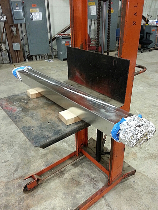
9510-000-MD-463495-01 MAIN INJECTOR RADIATION SHIELDING KICKER MASK LINER WELDED ASSEMBLY. This is the vacuum tube for this region of the accelerator. Machining details are in 9510-000-MD-463493-01 MAIN INJECTOR RADIATION SHIELDING KICKER MASK LINER MACHINING. |
|
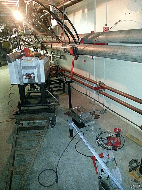
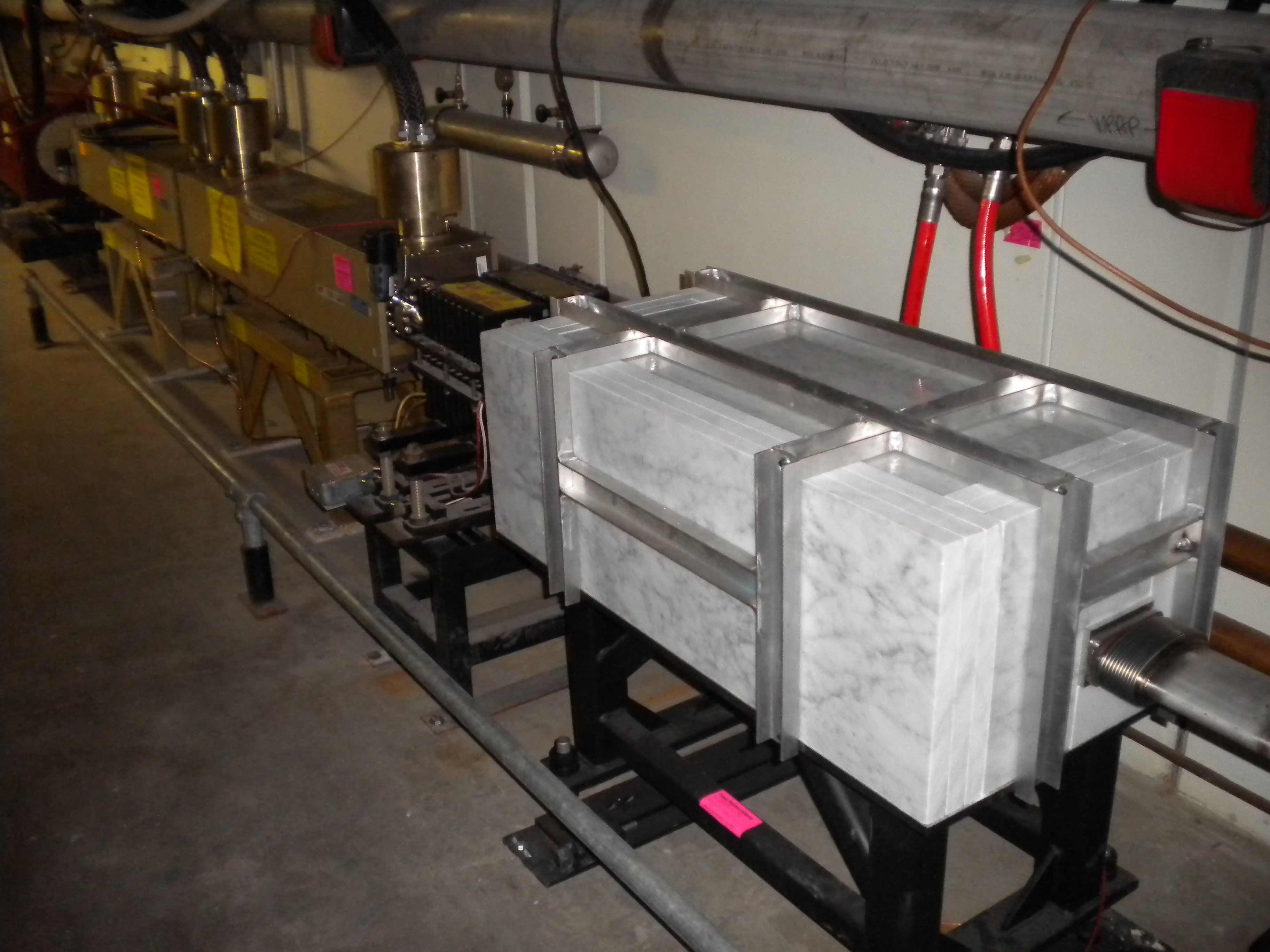
Mask Assembly and Stand on cart ready for installation at MI307 |
|
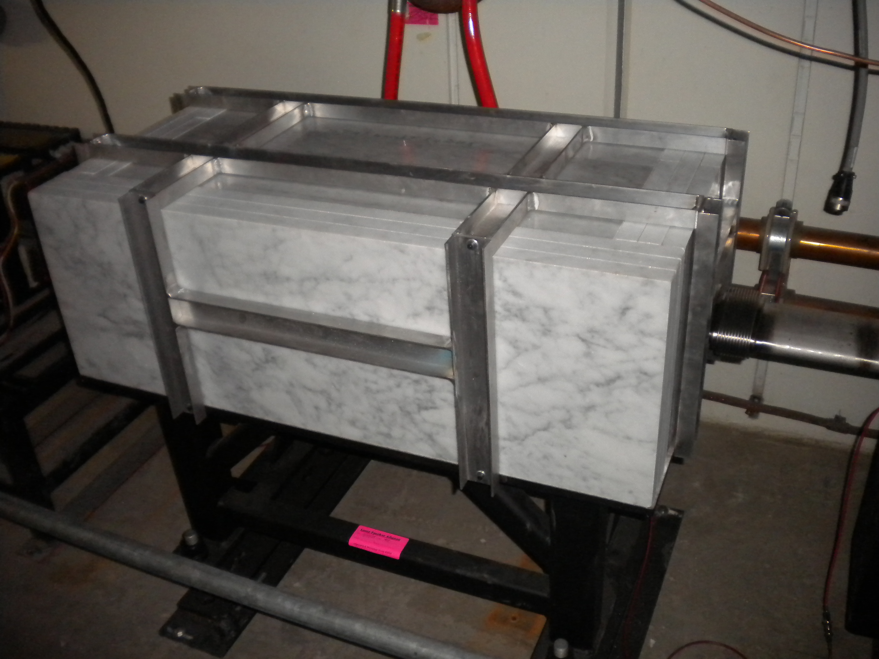
Mask as installed at MI307 viewed from upstream with H308 to the left. |
|
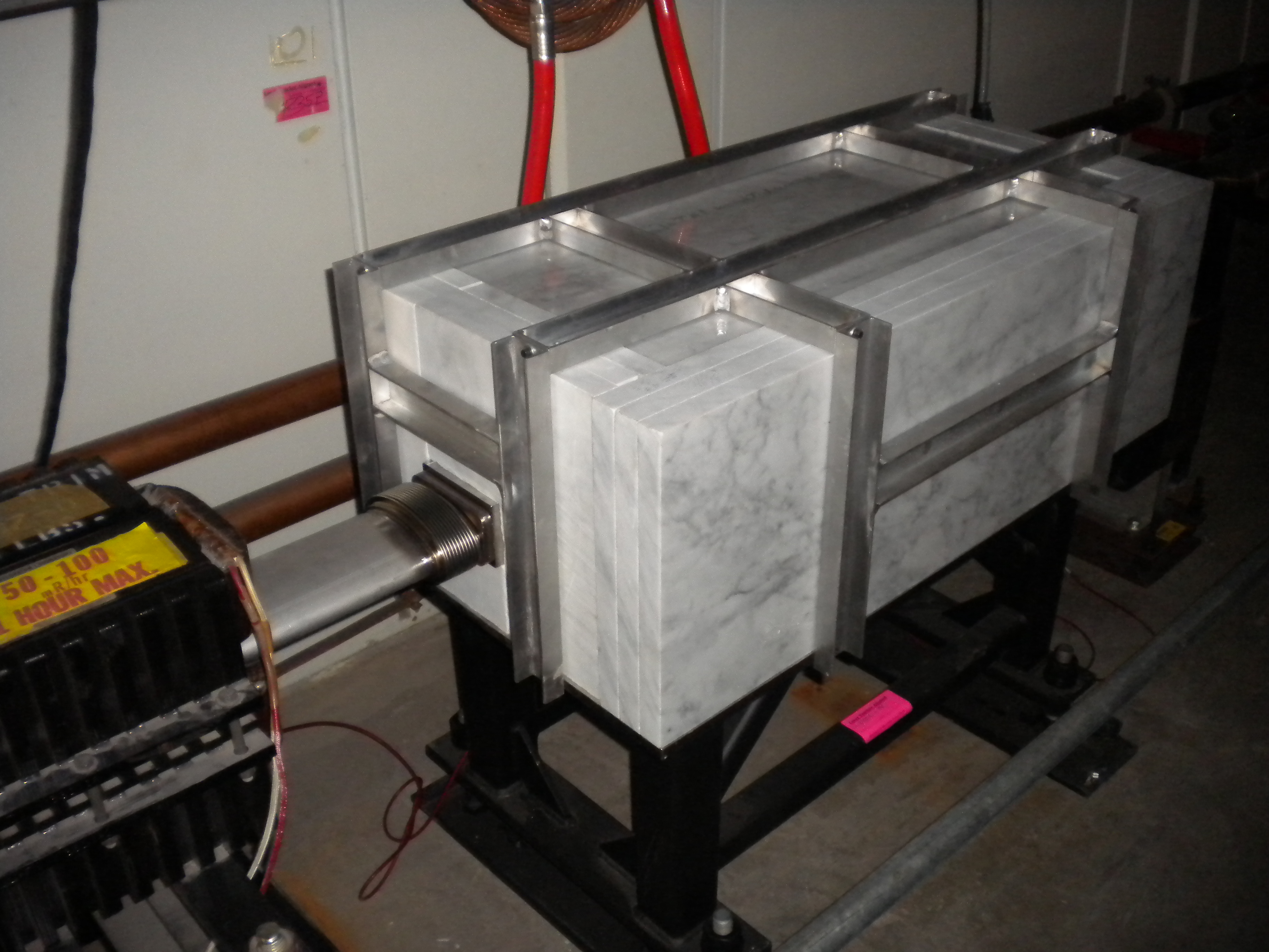
Mask as installed at MI307 viewed from downstream with H308 to the left. |
|
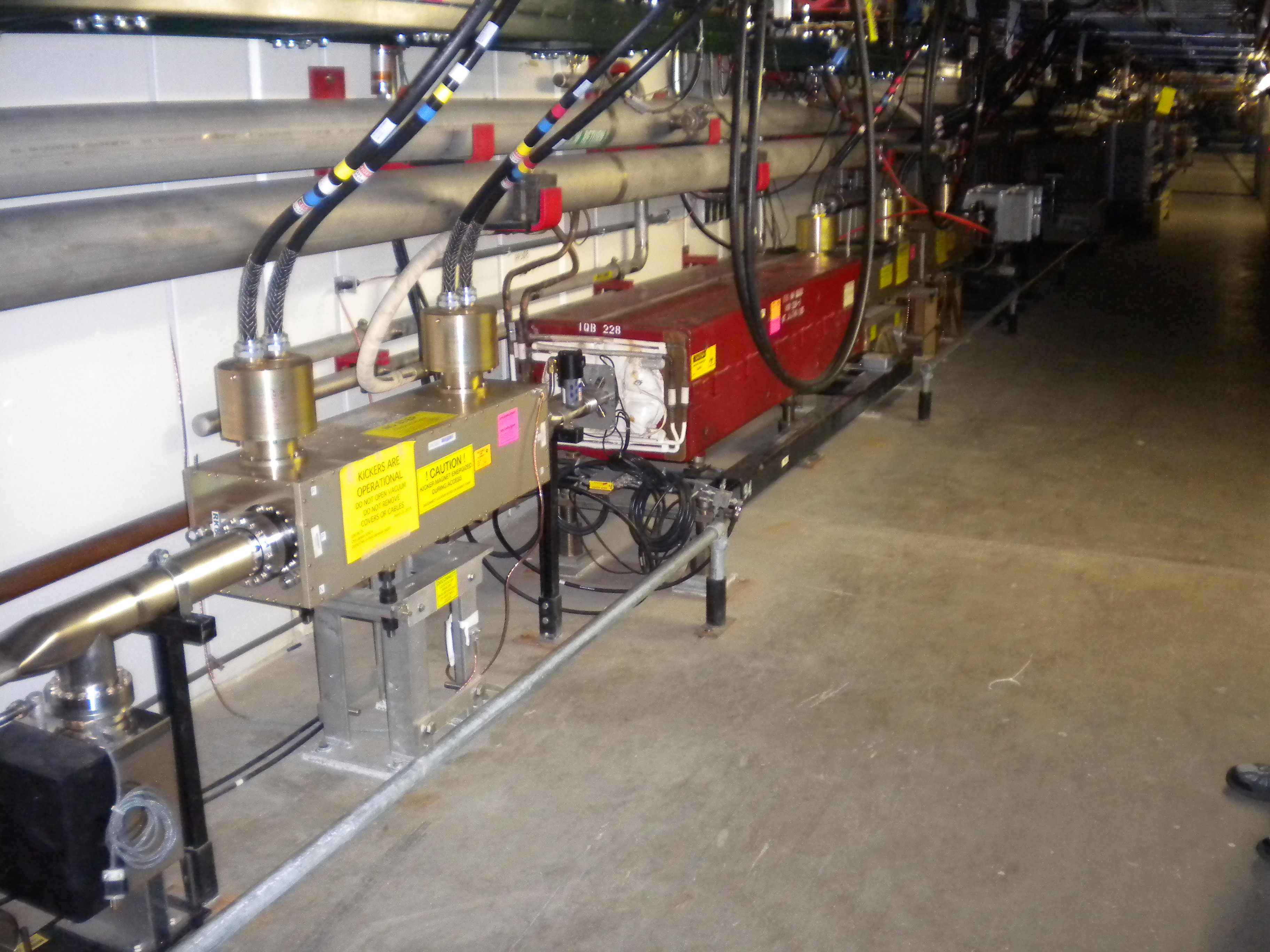
Mask as installed at MI307 viewed from upstream with H308, two kicker modules and Q308 to the left. |
|
MI308 area on 10/11/2013 viewed from downstream. From left to right we see: kicker module, Q308, kicker module, kicker module, H308, STMM307. Mask as installed at MI307 viewed from upstream with H308, two kicker modules and Q308 to the left. |