| Doc Number: MI-0007 |
|---|
A 150 Gev MI-11 to Tevatron Beamline Solution
Dave Johnson
Main Accelerator Department Fermi National Accelerator Laboratory
November 16, 1989
Introduction
Prior to the Breckenridge workshop, a satisfactory solution of the Main Injector to Tevatron 150 Gev/c transport line had not been found that was consistent with a shared extraction channel for 8 Gev/c antiprotons from the Accumulator. The lack of a 150 Gev/c Main Injector to Tevatron beamline was thought to be a critical deficiency in the Main Injector design proposal. Therefore, the design of an acceptable beamline became one of the topics of focus at the workshop. Several solutions were proposed r and two acceptable designs for the 150 Gev/c MI to Tevatron beamline emerged. One design ' utilized a dynamic beta insertion to modify the fi functions in the extraction straight section producing an acceptable 3 vertical dispersion match. This solution, however, addressed only the 150 Gev/c transport line optics. The other design, discussed here, utilized the nominal strong focussing lattice functions of the extraction straight section along with multiple vertical bends to 1) produce an exact vertical dispersion match of the 150 Gev/c transport line and 2) allow the injection of 8.9 Gev/c antiprotons through the extraction channel.
Description of the problem
Several constraints were placed upon the design of the beamline. The first constraint was to make the beamline fit between two accelerators where the horizontal separation between the adjacent straight sections was chosen to be 10 meters for siting and construction considerations. The elevation of the Main Injector (721.5'), in the MI-11 solution, was chosen to be .5715 meters below the Tevatron (723.275'). This orientation not only required matching the beta functions and horizontal dispersion between two planar machines; but now requires cancellation of the vertical dispersion introduced by the vertical extraction channel. It was the cancellation of this vertical dispersion that proved to be a challenge.
Other constraints arise from the multipurpose usage of the Main Injector straight section MI-60. The extraction/injection system must be able to accommodate:
150 Gev/c extracted protons for injection into the Tevatron,
120 Gev/c resonantly extracted protons for test beams to Switchyard,
and injection of 8.9 Gev/c antiprotons with a 95% normalized emittance of 30 p from the Antiproton Source. 4
The vertical orientation of the splitting stations in the current Switchyard
dictated a vertical extraction channel for the resonant extra.ction of 120 Gev/c test beams. The injection of antiprotons placed a beam size constraint on the lattice functions in the extraction channel and common beamline section. These must be small enough to accommodate the 8.9 Gev/c antiprotons while maintaining the dispersion match between all beamlines and the Main Injector.
Vertical Four-bump Solution
The orientation of the two accelerators fixed the length of the beamline to be approximately 210 meters. The angle between the extraction and injection straight sections is 10.78 degrees (188.072 mr). This requires about 941 kG m of bend to transport the beam from the MI to the Tevatron. Excluding the contribution of the horizontal c-magnet and lambertson used for the Tevatron injection, the transport line utilizes 8 Main Ring B2 dipoles at approximately 17 kG each for the horizontal transport. Most of the horizontal bending is required at the end of the transport line without interfering with the Tevatron RF. This leaves about 100 meters prior to the horizontal bends for establishing the proper vertical trajectory. The present solution separates the horizontal and vertical bending functions. A plan and elevation view of this solution is shown in Figure 1.
Four vertical bend centers are placed to exactly cancel the vertical dispersion, generated by the extraction lambertson, in the 150 Gev/c transport line. The bend centers actually make up two vertical "dogleg" translations with a minimum beamline distance between the two translations. The first translation provides the necessary elevation for the insertion of the central vertical bending magnets, VBl and VB2, above the MI dipoles. The initial vertical angle, qlamof 17.4 mr is generated by the extraction lambertson. The bend center VBl levels the beam off at an elevation sufficient to allow bend center VB2 to select between the 150 Gev/c proton injection line or the 120 Gev/c and 8 Gev/c beamline [not shown]. To enter the 8.9 Gev/c and 120 Gev/c beamline, the polarity of \`B2 is reversed (i.e. up bend). The second translation to the proper elevation for injection into the Tevatron is provided by VB2 and VB3. The vertical dispersion must be eliminated by VB3 for the perfect dispersion match between the Main Injector and the Tevatron.
To aid in the development of the solution; the quantity ![]() , discussed in reference 3, is
examined throughout the beamline for the particular plane of interest (i.e. vertical). For
this analysis the dispersion of the beamline elements are compared to zero so the D' S may be omitted. The normalized dispersion quantities ofĀ
, discussed in reference 3, is
examined throughout the beamline for the particular plane of interest (i.e. vertical). For
this analysis the dispersion of the beamline elements are compared to zero so the D' S may be omitted. The normalized dispersion quantities ofĀ ![]() and the phase
of the vector in c, x space were
calculated after each element of the beamline. The quantity is then written as
and the phase
of the vector in c, x space were
calculated after each element of the beamline. The quantity is then written as
![]()
A plot of c and x for each vertical bend is shown in
Figure 2. A vertical down bend, in the thin lense approximation, would be represented as a
horizontal vector to the left. The phase advance produced by the quads is simply a rotation
of this vector (i.e. invariant in the absence of dipoles). For comparison, an emittance
dilution of 1 n-mm-mr at 150 Gev/c and a Dp/p of .218% [ref. 3]
would be represented by the quantity ![]() = .0088. In c, x space
this would be a circle of radius .0938 as is shown in figure 2.
= .0088. In c, x space
this would be a circle of radius .0938 as is shown in figure 2.
To produce an achromat dogleg with two bends, one needs 360 degrees phase advance between the bends. With three or four bends only 180 degrees phase advance is required between the first and last bends. The last option was adopted for this design. To achieve the necessary vertical phase advance of the dispersion vector between the vertical bends to allow the dispersion in the Tevatron injection line to be canceled by VB3, the vertical beta function must be kept small between the lambertson and VB2 and large at VB3.
In addition, the horizontal beta functions functions between the MI and VB2 must be kept small enough, less than 118 meters, to allow the transport of 8.9 Gev/c pbars.
The vertical beta functions (and phase) through the vertical bending section are controlled by the quadrupoles Ql through QS. The horizontal dispersion and beta functions are matched to the Tevatron through the use of a mistuned horizontal achromat cell between Q7 and Q12. The central quads in the achromat allow the phase of the horizontal dispersion vector to be shifted through 120 degrees while keeping the lattice functions small.
The lattice functions of the transport line to the Tevatron are shown in Figure 3. The top row of arrows on the plots indicate the positions of the quadrupoles while the lower row indicate bend centers. Horizontal (vertical) focussing and bending are shown by up (down) arrow heads.
1"Report of the Accelerator and Beam Line Options Working Group, Proceedings of the 1989 Breckenridge Workshop"
2R. Gerig, "A Dynamic Lattice Insertion for Main Injector Extraction", these proceedings.
3R. Gerig, "A Dispersion Mismatch Criterion for the Main Injector to Tevatron Transfer Line", these proceedings
4 Fermilab Upgrade Phase II: The Main Injector, fig. 3.2.2
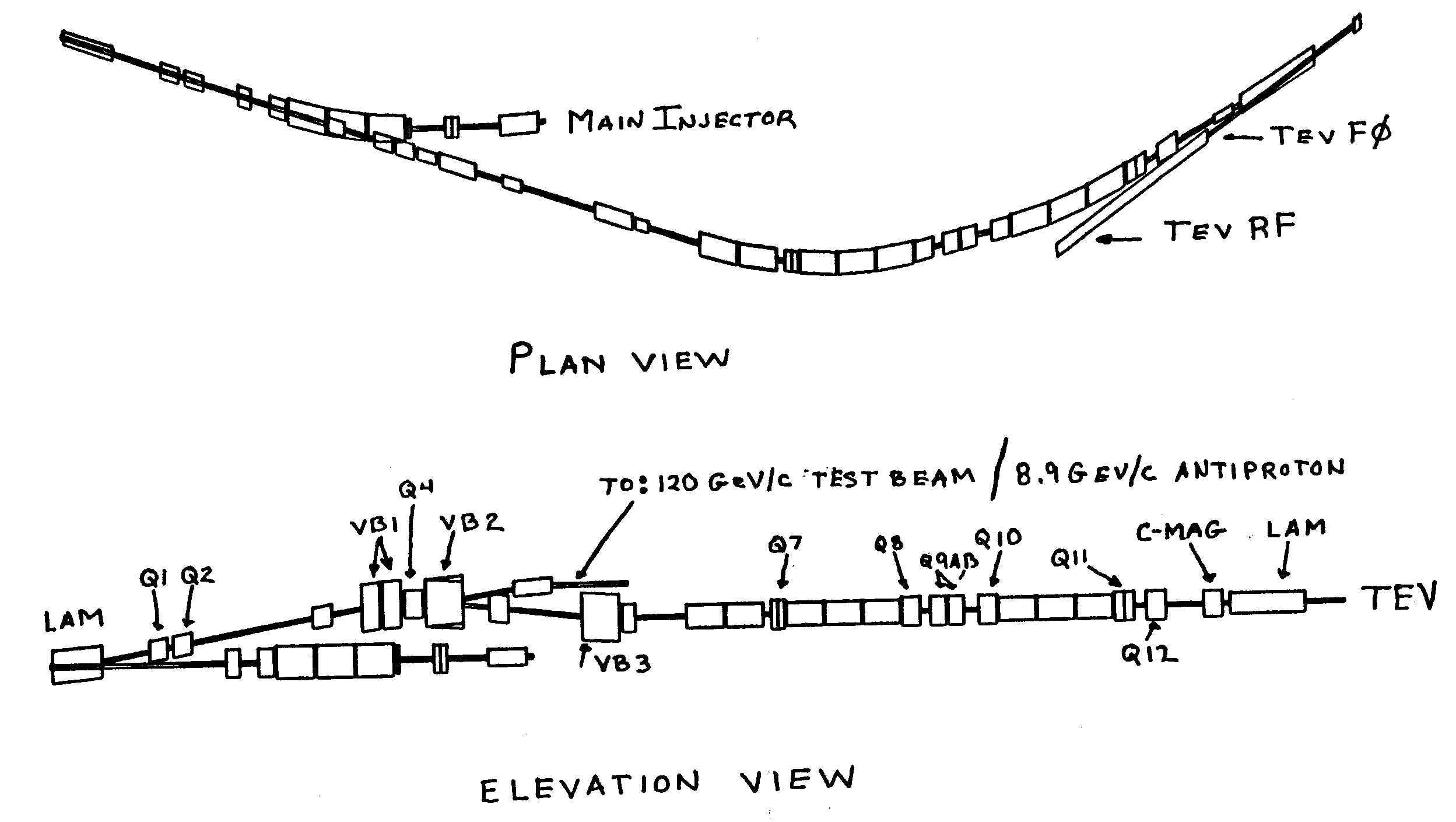
Figure 1: Plan and elevation view of the Main Injector to Tevatron transfer line for the MI-11 Main Injector solution. This utilizes four vertical dipoles to exactly cancel the vertical dispersion.
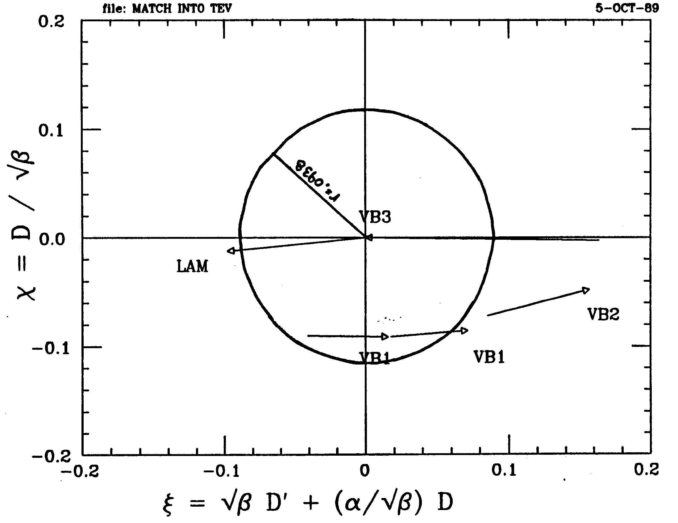
Figure 2: Plot of the normalized vertical dispersion vectors for the four vertical dipoles used to produce a vertical achromat.
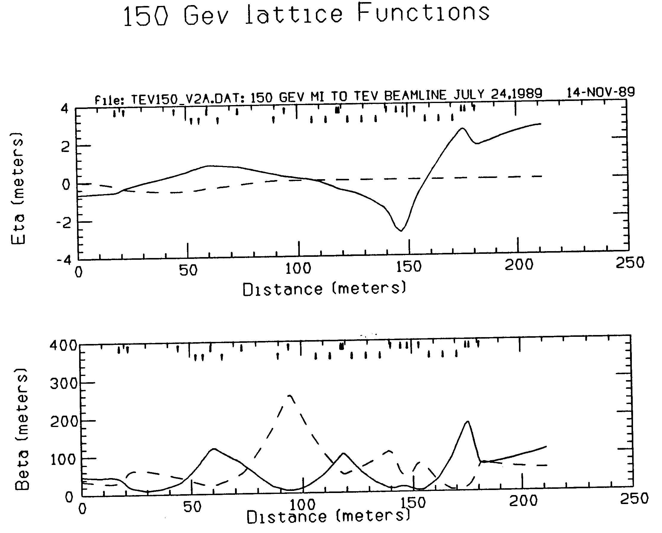
Figure 3: Lattice functions of the 150 Gev/c Main Injector to Tevatron transport line. Up (down) arrows on top row indicate horizontal (vertical) quadrupoles while the bottom row indicates horizontal (vertical) bend centers.