
Fermilab
| | | | | | | Doc Number: Beams-doc-1977
Version: 1.0
Category: Notes |
|---|
MI8 Beamline Collimation Design
Bruce C. Brown
Fermi National Accelerator Laboratory*
P.O. Box 500
Batavia, Illinois 60510
9/30/2005
*Operated by the Universities Research Association under
contract with the U.S.
Department of Energy.
1
Abstract
In response to the need to increase the intensity of proton beams
in the Main Injector while maintaining residual radiation levels which
permit hands-on maintenance, a program to provide collimation in the
Main Injector Ring and in the MI8 transfer line from the Booster to
the Main Ring is being designed. Design requirements and an initial
design concept for the MI8 collimation system will be provided in this
document. This effort is part of the Proton
Plan.
Topics
Introduction
In expectation of increased beam intensity requirements associated
with operation of the NuMI beamline, Residual radiation around the
Main Injector tunnel was examined prior to the 2004 Fermilab facility
shutdown (see
Residual Radiation Hints for Aperture and Alignment Issues in the Main
Injector). We concluded (among other things) that a small but
significant contributor to the residual radiation was losses of beam
due to tails of the Booster Beam which were not accelerated but were
scraped around the Main Injector at locations
which had only very little less aperture than other similar lattice
locations. By providing a more defined beam from the Booster, we will
reduce the losses from these tails which will reduce substantially the
number of hot locations in the MI Ring. Collimation in the MI8 Line
can provide this improved beam to the Main Injector. Tails from the
Booster Beam may contribute residual radiation at other, as yet
unidentified Main Injector locations.
In addition to more general sources of beam tails, measurements
of the beam motion induced by changes in the beam trajectory through
the Booster Extraction Septum (MP02) suggest that non-uniformity
of the fields in this bending magnet (including quadrupole and skew
sextupole terms) may be sufficient to create halo from some of the
extracted Booster beam (See
Multipole
fields in Booster extraction septum MP02). By proper placement
of the collimation system, one can begin commissioning by scraping
halo which would be created by this source (one selects the appropriate
phase advance). Since it imposes no undesirable constraints on
the collimator design, we will attempt to place collimators so that halo
from this source is cleanly collimated.
The design concept for this collimator system is based on the
Booster Beam Collimation system (see FERMILAB
BOOSTER BEAM COLLIMATION AND SHIELDING). The difference between
circulating and single pass beam collimation requires additional
collimators while the improved shielding provided by the MI8 tunnel allows
a more compact design. The following table compares the collimation
requirement for circulating beam in the Booster and one pass beam in the
MI8 transfer line.
Booster Collimators
|
MI8 Collimators
|
10 Hz at 5E12 Protons/pulse
|
10 Hz at 5E12 Protons/pulse (same)
|
2% Loss at 8 GeV plus low energy loss
|
1% Loss at 8 GeV (or more)
|
Multiturn circulating beam => collimators
1 Horizontal (radial outside)
1 Vertical (bottom)
|
One pass => collimators
4 Horizontal (inside, outside at two phases)
4 Vertical (top, bottom at two phases)
|
Tunnel not deep
|
Tunnel deep
|
Surface occupied
|
Surface not occupied
|
Air Activation not serious
|
Air Activation not serious
|
Sump Pumps in area actively carry water
|
Tunnel below water level -- not much sump activity
|
Ground Water not an issue
|
Ground Water not an issue
|
Early efforts on this collimation plan assumed that the radiation
issues from sump water and the resulting surface water were determined
by water levels. We have since discovered that Fermilab guidance for
these issues is based on the generation of nuclides in the materials
outside of the tunnel, independent of the water which is actually
present. For this reason, our design iterations must focus on this
limitation. A pair of collimation stations will be placed in the MI8
line approximately 90 degress apart in phase advance to capture
particles of large emittance at whatever phase they may exist.
The residual radiation from activation of the collimators is a
primary concern. Since marble is very difficult to activate and
since it provides a good shield for the low energy gamma rays which
are the primary residual radiation produced when iron is activated,
we are designing a collimation system in which the shower from the
hadronic interactions takes place in stainless steel and iron but
beyond that region we place sufficient marble to reduce the radiation
exposure for regions adjacent to the collimators (for both work in
that area and for those passing through the area.
A design which provided a pair of opposing jaws (top and bottom or
left and right) at one location would appear to have some advantages,
at least conceptually. The demands of low maintenance (motion system
well shielded) severely restrict those options. Available collimators
from external beams were considered but they were not sufficiently
massive and the motion and vacuum issues made this an unacceptable
choice. The current design employs jaws at right angles which allow
horizontal and vertical collimation at the same location. With this
starting point, the Booster collimators provide an excellent reference
design.
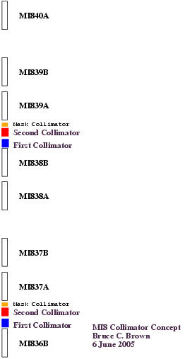
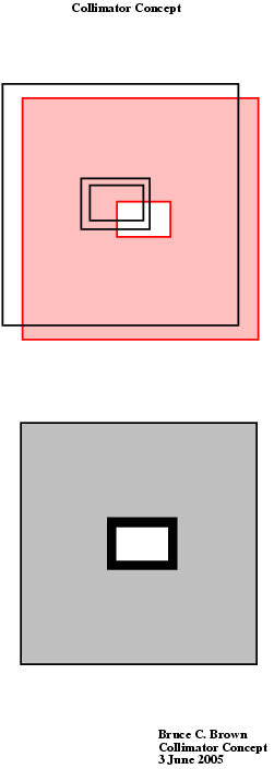
The MI8 Collimator design will intercept the beam in stainless
steel vacuum boxes (part of the MI8 vacuum system) surrounded by
massive steel absorbers with external marble shielding. As in the
Booster collimation system, the motion system will be external to the
entire collimator system. A pair of these remotely positioned
collimators will be placed in 5.2 m open space in an MI8 half-cell in
which the focusing is provided by gradient magnets. One collimator
will provide scraping on one horizontal and one vertical edge (bottom
and outside, for example) while the next will scrape the other sides
(e.g. top and inside). They will be followed by a fixed collimation
mask which will protect the next magnet. In order to scrape large
emittance particles which happen to be at small displacement but large
angle at the location of the initial collimation, a second
collimator-mask set will be placed two half cells downstream (about 90
degrees phase advance). This arrangement is illustrated in the
following figure.
MI8 Collimator Concept
| Layout |
End View |
|
|
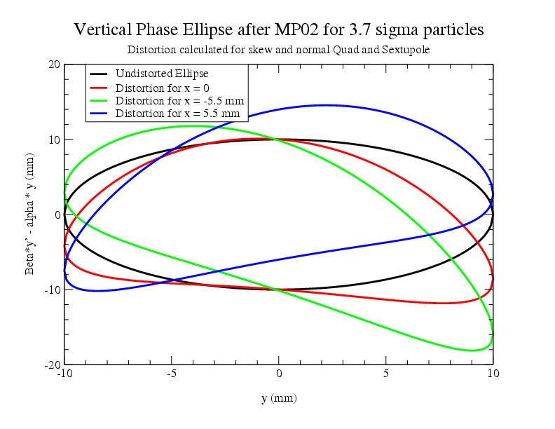
Frequently one assumes that magnet field quality issues will not
impact the beam quality for single pass transport. To check this
assumption for a given dipole magnet, on can calculate the distortion
for a phase space ellipse. In a vertical bending dipole, one expects
the bend to be uniform. For a bend angle Theta, the error y'
introduced by a field error dB/B is y' = (dB/B)(Theta). If we
calculate this error along a vertical slice across the MP02 magnet and
assume the fields from
Multipole fields in Booster extraction septum MP02 (Beams-doc-1573), one can
calculate the distortion of the phase ellipse for that slice of beam.
The vertical aperture available for the extracted beam in MP02 is
about plus/minus 10 mm. Using the design Booster lattice with Beta_v
= 20 m one finds that the beam at this distance from beam center is at
3.7 sigma in the distribution so it corresponds to 0.1% of the beam
intensity. The MI8 line could transport such beam without loss --
probably even with distortion. However, with the fields reported in
Beams-doc-1573, one will have a substantial distortion of the extreme
beam particles. The figure shows the undistorted phase ellipse (using
the normalized plot (y, (beta*y' - alpha * y)) and the distortion for
the central vertical slice and the vertical slices displaced by 3.7 sigma
in the horizontal dimension. Similar distortions will produce halo
in the horizontal phase space. Of course, the distortions from harmonic
field errors will be smaller for beam particles nearer the beam center.
Since the outer portions of the Booster beam are distorted by MP02,
one would wish to collimate them. If the distortion were produced at
a definite phase, one could choose a location downstream with suitable
phase advance to remove the distorted beam. However, with large
distortions, different parts of the halo will appear at different
phase advance locations. In addition, the matching section between
MP02 and the higher beta FODO section of the MI8 line introduces 90
degrees of additional phase advance for the horizontal motion so that
a location suitable for removing vertical halo will be different from
that for horizontal halo. Some differences will remain among possible
collimator locations but we do not find a clear optimum based on what
we currently know about the MP02 fields. It should be noted that the
direct measurement of the bend field in the central region (see Beams-doc-462)
showed a smaller field error but one of the same general magnitude.
Direct measurements of the skew magnetic fields with coils are not
available.
MI8 Lattice -- Locations for 90 degree and 270 degree phase advance from MP02
Location for Vertical Mark
|
Dist.
|
mu/2pi
|
Location for Horizontal Mark
|
Dist.
|
mu/2pi |
MP02
|
5.371
|
0.146
|
MP02
|
5.371
|
0.162
|
H803_1
|
51.598
|
0.399
|
V802_3 |
42.013 |
0.420 |
HP806
|
77.089 |
0.855
|
VP805 |
68.451 |
0.747 |
LM809B
|
112.291 |
1.375
|
HT808 |
90.311 |
1.420 |
PDD_R (in 813 halfcell)
|
177.634 |
1.917
|
PDD_R (in 811 halfcell)
|
145.427 |
1.916 |
PGD_818A
|
238.843 |
2.397
|
PGD_816B |
214.677 |
2.423 |
PGD_822A
|
299.259 |
2.912
|
PDD (1st in cell 820) |
277.147 |
2.915 |
HP826
|
360.495 |
3.395
|
PGD_824B |
334.766 |
3.382 |
PGD_830B
|
424.461 |
3.932
|
PGD_829A |
403.964 |
3.934 |
PGD_834B
|
484.508 |
4.439
|
VP833 |
465.204 |
4.436 |
PGD_838B
|
544.921 |
4.907
|
PGD_837A |
524.056 |
4.902 |
PGD_842B
|
604.963 |
5.371
|
VP841 |
585.660 |
5.392 |
| PGD_846B |
664.639 |
5.871 |
PGD_845B |
649.627 |
5.923 |
Based on a representation of the MI8 Lattice in MAD, a calculation
of the longitudinal profile of beam with specified emittance has been
carried out using and Excel spreadsheet. In the following graphs, we
examine the trajectories of particles with y = 10 mm, with x = 5.3 mm
at MP02 (cosine-like) and particles with that emittance on the
sine-like trajectories (each of which corresponds to the part per 1000
edge of the beam) and with dp/p = 0.003. It appears that both
horizontal and vertical collimation for a range of phases in the
betatron motion is provided while momentum tails will be collimated to
some degree. A more detailed look at these issues will be
accomplished along with the simulations of collimation at alternate
locations along the MI8 line.
MI8 Beam Profile Plots
| Beam Profile |

|
|
Design Properties for MI8 Collimators
| Property
|
First Collimator
|
Second Collimator
|
| Emittance
|
20 pi-mm-mr (h or v)
|
20 pi-mm-mr (h or v)
|
| ßh
|
35 m
|
32 m
|
| ßv
|
16 m
|
20 m
|
| 0.1% half-width (3.72 sigma)
|
13 mm
|
12.4 mm
|
| 0.1% half-height (3.72 sigma)
|
9 mm
|
9.8 mm
|
| 0.1% half-width (3.03 sigma)
|
10.65 mm
|
10.15 mm
|
| 0.1% half-height (3.03 sigma)
|
7.4 mm
|
8 mm
|
| Dispersion (horizontal)
|
<3 m
|
<3 m
|
| Momentum offset for dp/p = 0.001
|
<2 mm
|
<2 mm
|
Simulations of the radiation using MARS were carried out using a
number of configurations. The iron configuration which matched the
Booster collimators was found more than adequate but since the
residual radiation was the driving design feature, and the surface
radiation was not critical, designs using marble to replace portions
of the steel were examined. An iteration with 5" of marble shielding
was found to provide very low residual radiation with a much smaller
iron absorber. Less iron implies less weight and fewer demands to
support and move the device. After iterations which examined dose to
adjacent control cabling and nuclide production in the materials
outside the tunnel walls, the following configuration was found to
satisfy the design needs with about 1% loss in a collimator pair and
the beam intensities shown in the table for both Booster and MI8. The
driving design criteria is that the residual radiation be <100
millirem/hr on contact after 30 days of activation and 1 day of
cooldown. Note that the design includes some iron where the table
might suggest marble in order to provide mechanical support as
needed. When further simulations are complete, additional substitution
of iron for marble may be used to optimize the configuration for
radiation concerns.
Material
|
Units
|
Vacuum
|
Stainless
|
Iron
|
Marble
Side
|
Marble
Ends (2)
|
Length
|
Inch
|
|
47
|
35
|
35
|
5
|
Inside Wall
|
Inch
|
0
|
2 x 2
|
3.5 x 3.5
|
20(h) x 26(w)
|
3.5 x 3.5
|
Outside Wall
|
Inch
|
2 x 2
|
3.5 x 3.5
|
20(h) x 26(w)
|
30(h) x 36(w)
|
30(h) x 36(w)
|
Wall Thickness
|
Inch
|
|
0.75
|
8.25(h) or 11.25(w)
|
5
|
13.25 or 16.25
|
The design goals of this collimator system will require the review of
a number of radiation issues. We will document issues and a current
understanding of their implications in this section. We will assess the
radiation effects assuming a loss of 1% of the beam on each collimator
pair or a total of 2% of the Booster Beam which is assumed as 5E12 protons
per pulse with a repetition rate of 10 Hz.
- Prompt radiation issues can be divided into issues for single
event accidents and effects of normal operation. Normal operation
effects are further divided by effects for occupied and for unoccupied
spaces. Since the Main Injector and MI8 line tunnels are covered by
24.5 feet of earth, there is adequate shielding for normal
operation. There are no locations near this installation which are
occupied but it would be adequately shielded if they were. Thermal
protection will be required to prevent damage to the collimators under
accident conditions. Prompt radiation issues will not impose
additional single event design constraints.
- Air Activation with this collimator design should not pose any
constraints on either tunnel air flow during normal operation nor any
delay for access during shutdown.
- The MI8 Tunnel is below most local water and the sumps are normally
dry. But the Fermilab protocol for assuring compliance with surface
water rediation requirements is based on the number of radioactive nuclei
created, without any assumptions about their concentration or dilution
in ground water. Calculations for the collimator design are underway
to assure that these requirements are met.
- The primary design effort is concerned with the residual dose at
the surfaces of the devices as dictated by the need to be able to
perform hands-on maintenance in the area. This collimation system has
been designed to keep the radiation as measured at one foot to less than
100 millirem/hr The collimators will be set to achieve this level of
activation given the transverse motion stability which can be achieved.
If the motion during a given operational period is greater than anticipated,
The collimators can be set to achieve less scraping of the beam which passes
symmetrically through the beam line.
Since this collimation system will create a continuous radiation source, suitable
documentation which reviews and documents the above points will be written
and the appropriate Beams Division safety documents will be reviewed and revised
as required.
Further Steps
The installation of these collimators is planned for the FY06 shutdown. Mechanical
design is nearly complete and procurement and fabrication is underway. The location
shown in this document will be reviewed to see if further optimization can provide
a useful improvement based on loss simulations for various beamline locations using
the measured lattice and the beam distortions at MP02 discussed above. The final
optimization of the steel and marble for the collimator will be carried out using
additional MARS studies.